 English
 Deutsch
 Русский
 Español
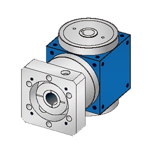


Single-Stage Cylindrical Gear Reducer:
A single-stage cylindrical gear reducer is suitable for reduction ratios ranging from 3 to 5. The gear teeth can be straight, helical, or herringbone. The housing is typically constructed from cast iron or welded steel plates. Roller bearings are commonly used for bearings, while sliding bearings are reserved for heavy loads or extremely high speeds.
Two-Stage Cylindrical Gear Reducer:
Two-stage cylindrical gear reducers are categorized into three types: expanding, split, and coaxial, suitable for reduction ratios ranging from 8 to 40.
- Expanding Type: Features a high-speed long tail helical gear and low-speed gears that can be straight or helical. Its asymmetric arrangement demands greater stiffness from bearings and shafts, minimizing the unbalanced load distribution across the gear width to reduce shaft bending and deformation. Widely used due to its simple structure.
- Split Type: Generally adopts high-speed splitting. As gears and bearings are symmetrically arranged, forces acting on gears and bearings are more uniform. Commonly used in high-power and variable load scenarios, though its structure is more complex.
- Coaxial Type: Larger axial dimensions, longer intermediate shaft, and lower rigidity characterize this reducer. It is typically used where input and output shafts are coaxial.
Single-Stage Bevel Gear Reducer:
Single-stage bevel gear reducers are suitable for reduction ratios ranging from 2 to 4. The transmission ratio should not be too large to reduce the size of bevel gears for ease of processing. It is only used for transmitting power between two axes that intersect vertically.
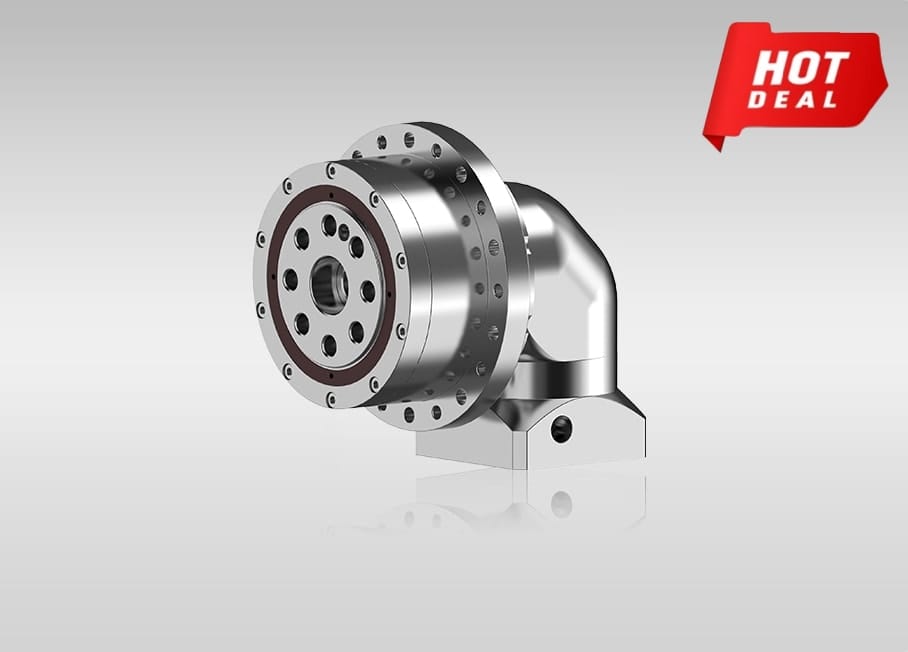
Bevel and Cylindrical Gear Reducer:
Bevel and cylindrical gear reducers are suitable for reduction ratios ranging from 8 to 15. Bevel gears are arranged in the high-speed stage to reduce the size of the bevel gears. Bevel gears can be straight or helical, while cylindrical gears are mostly helical, compensating for some axial forces from the bevel gears.
Worm Gear Reducer:
There are various types of worm gear reducers, including cylindrical worm gear reducers, circular arc enveloping worm gear reducers, conical worm gear reducers, and worm-wheel reducers, with cylindrical worm gear reducers being the most widely used. Worm gear reducers are suitable for reduction ratios ranging from 10 to 80. They have a compact structure and a high transmission ratio but low transmission efficiency. They are suitable for low-power and intermittent operation scenarios. When the circumferential speed of the worm is V ≤ 4-5 m/s, the worm is usually positioned below for better lubrication and cooling conditions. When V ≥ 4-5 m/s, the stirring loss of the oil is significant, and the worm is generally placed above.
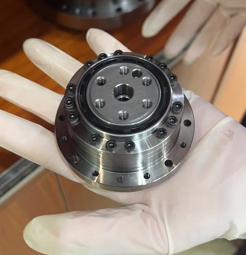
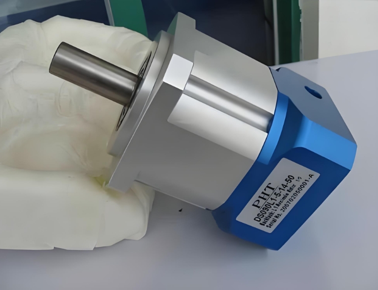
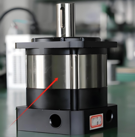
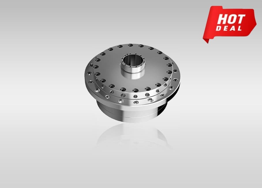
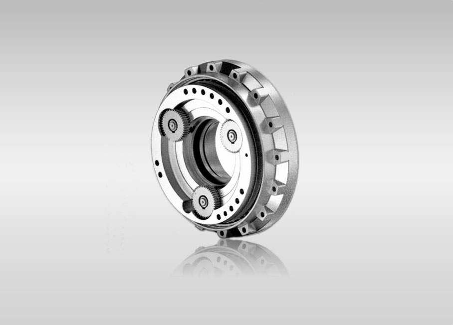
Due to the structural characteristics of planetary reducers, a single stage typically ranges from a minimum reduction of 3 to a maximum of around 10. Common reduction ratios include 3/4/5/6/8/10, with the number of stages generally not exceeding three, although some may have more. Custom reducers can have up to four stages.
Compared to other reducers, planetary reducers exhibit high rigidity, precision (single-stage completion in 1 minute), high transmission efficiency (single stage 97%-98%), high torque, compact size, and lifelong maintenance-free characteristics. Because of these features, planetary reducers are often installed on stepper motors and servo motors to reduce speed, increase torque, and match inertia.
Quote Now