 English
 Deutsch
 Русский
 Español
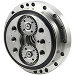


 Download PDF
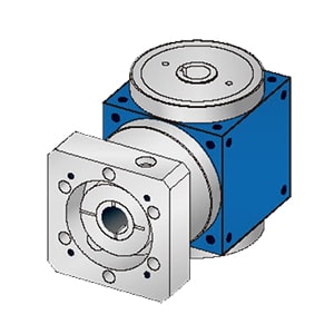
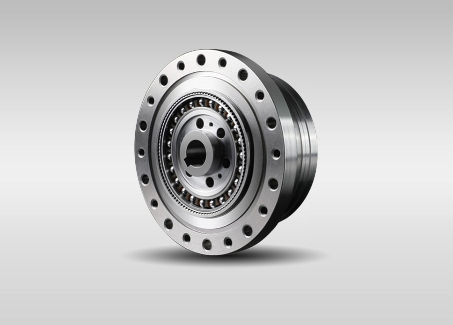
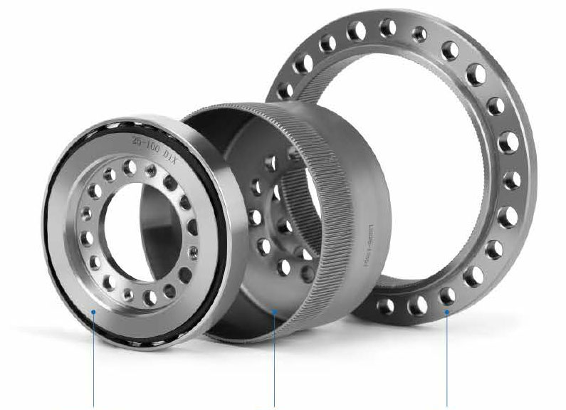
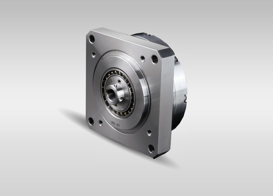
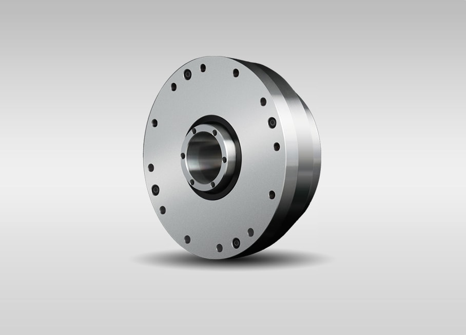
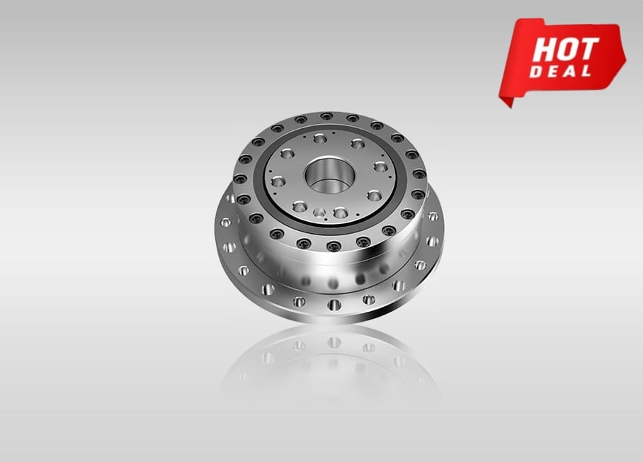
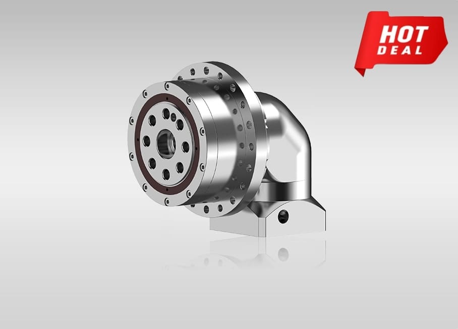
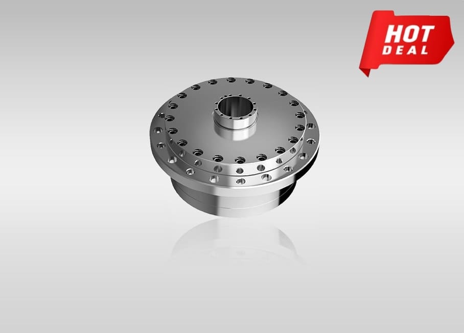
Description of WSS series harmonic reducer
Specification of WSS series
Each product is assembled with precise cross roller bearing for supporting external loading (Output flange)
| Type | Basic rated load | Allowable static moment Mc |
Weight | ||||
|---|---|---|---|---|---|---|---|
| Basic rated dynamic load Cr | Basic rated static load Cr | ||||||
| KN | kgf | KN | kgf | Nm | kgfm | kg | |
| 14 | 4.7 | 480 | 6.07 | 620 | 41 | 4.2 | 0.22 |
| 17 | 5.3 | 540 | 7.55 | 770 | 64 | 6.5 | 0.3 |
| 20 | 5.8 | 590 | 9.0 | 920 | 91 | 9.3 | 0.38 |
| 25 | 9.6 | 980 | 15.1 | 1540 | 156 | 16 | 0.6 |
| 32 | 15 | 1530 | 25.0 | 2550 | 313 | 32 | 1.1 |
Starting torque of WSS series
| Type / Reduction ratio |
11 | 14 | 17 | 20 | 25 | 32 |
|---|---|---|---|---|---|---|
| 50 | 2.0 | 4.1 | 6.1 | 7.8 | 15 | 31 |
| 80 | 1.8 | 2.8 | 4 | 4.9 | 9.2 | 19 |
| 100 | 1.5 | 2.5 | 3.4 | 4.3 | 8 | 18 |
| 120 | - | 2.3 | 3.1 | 3.8 | 7.3 | 15 |
| 160 | - | - | - | 3.3 | - | - |
Moment load table of WSS(WSG) series
| Model | Design value | Permissible value at start and stop | Instant permissible value |
|---|---|---|---|
| WSS(LSG)-14 | M b di 20Nm | M b peak 40Nm | M b max 80Nm |
| F t di 180N | F t peak 320N | F t max 560N | |
| F a di 180N | F a peak 320N | F a max 560N | |
WSS(LSG)-17 |
M b di 30Nm | M b peak 60Nm | M b max 120Nm |
| F t di 230N | F t peak 400N | F t max 700N | |
| F a di 230N | F a peak 400N | F a max 700N | |
WSS(LSG)-20 |
M b di 42Nm | M b peak 80Nm | M b max 168Nm |
| F t di 270N | F t peak 480N | F t max 830N | |
| F a di 270N | F a peak 480N | F a max 830N | |
WSS(LSG)-25 |
M b di 80Nm | M b peak 160Nm | M b max 313Nm |
| F t di 440N | F t peak 770N | F t max 1320N | |
| F a di 440N | F a peak 770N | F a max 1320N | |
WSS(LSG)-32 |
M b di 220Nm | M b peak 440Nm | M b max 890Nm |
| F t di 900N | F t peak 1600N | F t max 2700N | |
| F a di 900N | F a peak 1600N | F a max 2700N |
PRINCIPLE OF HARMONIC GEAR REDUCER
Harmonic drive was invented by American inventor C. Walt Musser in mid-1950s.
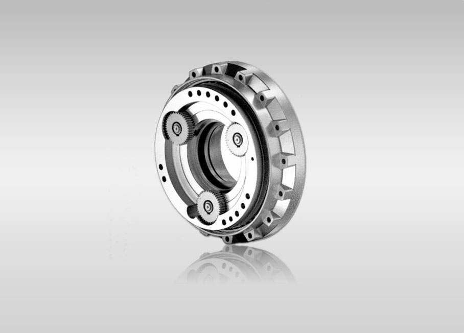
1. Composition of harmonic gearbox
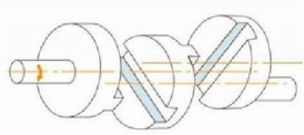
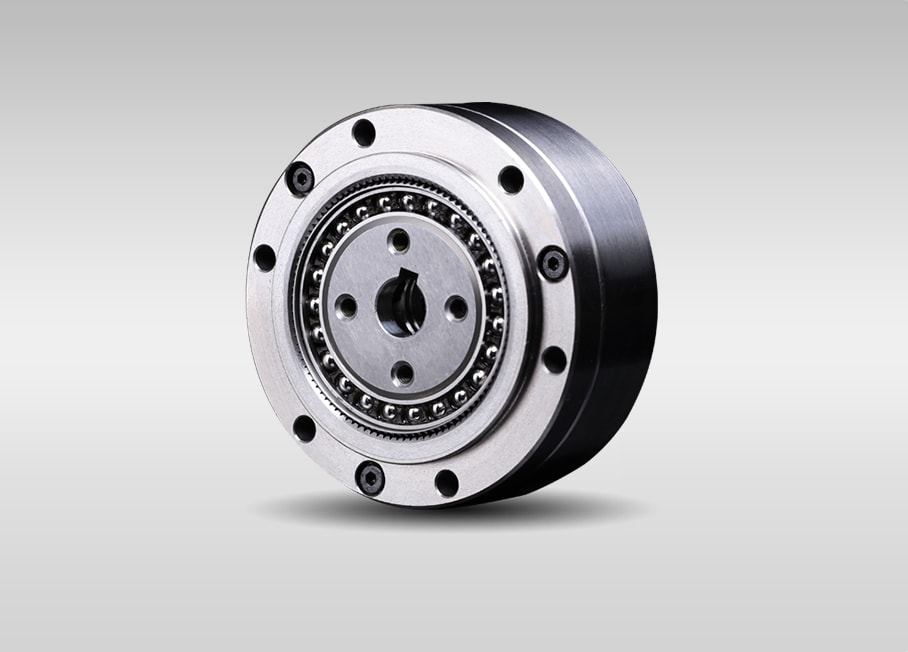
harmonic gearbox has three basic components: a wave generator, a flex spline and a circular spline.
Wave generator: it is made up of a ball bearing and an elliptical cam.The wave generator is usually attached to the input end, the inner ring of the bearing is fixed around the cam causing the outer ring of the bearing deforms to an elliptical shape.
Flex spline: it is an elastic thin-walled component with gear teeth on outer surface . It is usually fitted to output end .
Circular spline: it is a rigid steel ring with internal teeth. It usually has two more teeth than the flex spline, and generally mounted onto a housing.
2. Principle of harmonic gearbox
As a reducer, the harmonic gearbox is often in a status as: the wave generator drives, the circular spline is fixed, the flex spline is output end.
When the wave generator is put inside of the flex spline, the flex spline is forced into an elliptical shape causing the flex spline teeth to engage with the tooth profile of the circular spline along the major axis of the ellipse, with the teeth completely disengaged across the minor axis of the ellipse.
The rotation of the wave generator makes the flex spline deform continuously, the teeth change operating state in the process of engagement and disengagement, thus the motion transmission between wave generator and flex spline is realized
3. Characteristics of harmonic gearbox
1. High accuracy: a good percentage of its teeth are meshed at all times, and are engaged at two zones 180 degrees apart. This means influences of tooth pitch errors and accumulated pitch errors on rotational accuracy are neutralized, which assures high positional and rotational accuracy.
2. High speed reduction ratio: a harmonic gearbox has high single-stage reduction ratios of 1/30-1/500.Three basic components along same axle without complex structures can provide high reduction ratios.
3. High torque capacity: each tooth is subjected to a negligible amount of force yet provides a high torque capacity because of the way the teeth come into contact with each other and because a good percentage of the teeth in the flex spline are engaged at all times.
4. Small-sized and light weight: while being less the size of conventional gearing mechanisms and less the weight, the harmonic gearbox provides the same levels of torque and speed reduction ratios as its conventional counterparts enabling machinery and equipment to be made smaller and lighter.
5. Superior efficiency and long life time.
6. Quiet and minimal vibration operation.
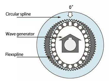 The flex spline is forced into an elliptical shape by the wave generator causing the flex spline teeth to engage with the tooth profile of the circular spline along the major axis of the ellipse, with the teeth completely disengaged across the minor axis of the ellipse.
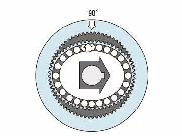 As the wave generator rotates clockwise with the circular spline fixed, the flex spline is subjected to elastic deformation and its tooth engagement position moves turning relative to the circular spline.
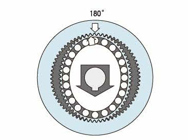 As the wave generator rotates 180 degrees dock wise, the flex spline moves counterclockwise by one tooth relative to the circular spline.
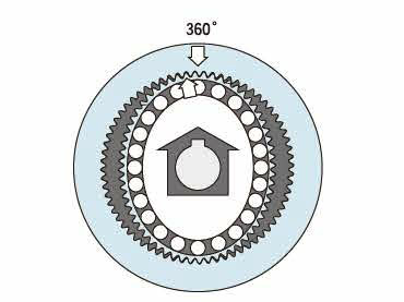 For every one full rotation clockwise (360 degrees) of the wave generator, the flex spline moves counterclockwise by two teeth relative to the circular spline because the flex spline has two fewer teeth than there are on the circular spline. in general, this movement is treated as output performing.
Mesh tooth by tooth progress
- Gear toothing capacity increased by 15%
- Temperature rise decreased by 8-10 degrees
- Reduced gear fatigue pitting contact area
- Service time exceeded 15000 hours
About WS tooth profile
We have made some upgrades based on the traditional theoretical double arc profile. The tooth profile formed by the original two curve. Continuous arc curve is optimized as a continuous arc curve with multiple segments of curvature. To ensure that the gears of reducer are properly meshed, while protecting the risk of grease failure after grease is squeezed by reducing relative sliding friction.
Based on the δ tooth shape, the load capacity is increased by 15%, the temperature rise is reduced by 8-10 degrees, the gear fatigue pitting contact area is reduced by more than 30%, continuous running and service life is over 15000 hours, which improves the overall performance of the harmonic gearbox.
During development, the formation of the soft tooth profile can be determined by the radial displacement of the genera tor. Different gear reduction ratios can be fitted with various tooth profiles And the mesh backlash can be conveniently adjusted according to actual conditions. Keep the gearbox in the best working condition.
About Fubao Harmonic Reducer
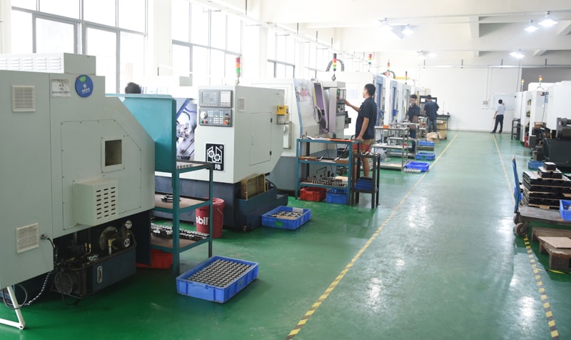
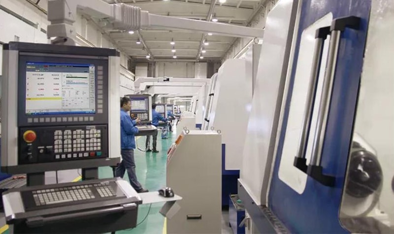
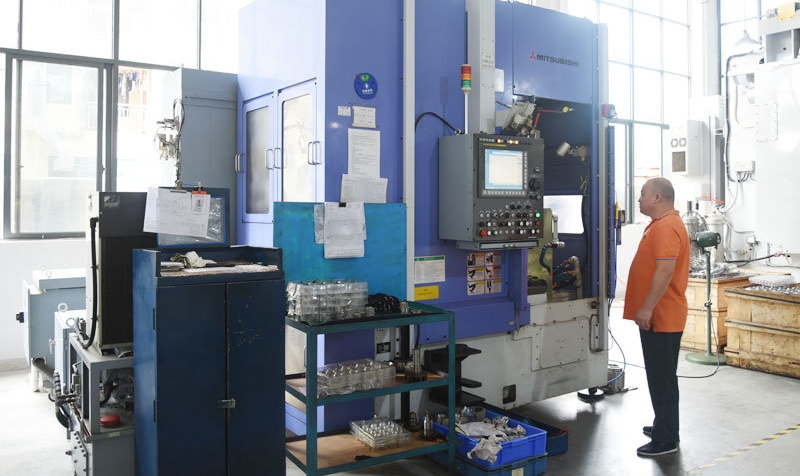
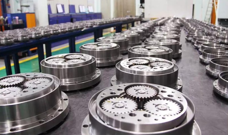
Dongquan Fubao Motor Technology Co.,Ltd, is a specialized company engaged in the research and development of high-precision harmonic gearbox. The company has 30000 square meters of standard plant, using the world's top production and inspection equipment, and has strict quality control in all links from raw materials to finished products, so as to ensure the quality of products.
Completely independent development, the company's R& D center has been identified as the provincialR& D center of high-tech enterprises. In the field of harmonic drive, has a number of national invention patents and national utility model patents.
The precision harmonic gearbox developed and produced by our company has the characteristics of high reliability, high precision, high torque, long service life, large speed ratio, small volume, etc. the products are widely used in the fields of robot, aerospace equipment, CNC machine tools, semiconductor manufacturing equipment, precision machinery automation control, etc., and are committed to changing the world's automation pattern.
Naming Rules
U: Completely unit
C: Component
II: Simple Cross Slider Type
Blank: Standard
M: Compact Mini
| Series | Type | Reduction ratio(Note 1) | Structure Code | Style | |||||
|---|---|---|---|---|---|---|---|---|---|
| WSS WSN WSG WSD WFS |
11 | 50 | 80 | 100 | null | U: Completely unit C: Component |
I: Simple Standard Type II: Simple Cross Slider Type |
Blank: Standard M: Compact Mini |
|
| 14 | 50 | 80 | 100 | 120 | |||||
| 17 | 50 | 80 | 100 | 120 | |||||
| 20 | 50 | 80 | 100 | 120 | 160 | ||||
| 25 | 50 | 80 | 100 | 120 | |||||
| 32 | 50 | 80 | 100 | 120 | |||||
| 40 | 50 | 80 | 100 | 120 | |||||
Seal Ring's Size Description
| Series | Model | Circular spline | flex spline | ||
|---|---|---|---|---|---|
| Seal ring size | Slot size | Seal ring size | Slot size | ||
| WHT-I WUT-L |
14 | 36.5*0.6 | |
53*1.5 | |
| 17 | 45*1 | |
64*1 | |
|
| 20 | 54*1 | |
73*1.5 | |
|
| 25 | 68*1 | |
90*1.5 | |
|
| 32 | 88*1.5 | |
119*1.5 | |
|
| 40 | 108*1.75 | |
143*2 | |
|
Terms and Definitions
Starting torque: It is the minimum torque value applied to the input end at which the harmonic gearbox first starts to rotate with no load.
Backlash: The clearance between flex spline tooth profile and circular spline tooth profile.
Rated torque: It indicates allowable continuous output torque at rated input speed.
Permissible peak torque at start and stop: It's the maximum torque as a result of the moment of inertia of the output load during acceleration and deceleration.
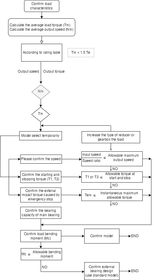
Permissible maximum value for average load torque: It's the maximum torque when the harmonic gearbox keeps continuous operation.
Permissible maximum momentary torque: It is the momentary peak torque the harmonic gearbox may be subjected to the event of a collision or emergency stop.
Permissible maximum input rotational speed: Don't exceed the permissible rating.
Permissible average input rotational speed: It's the average value of input speed.
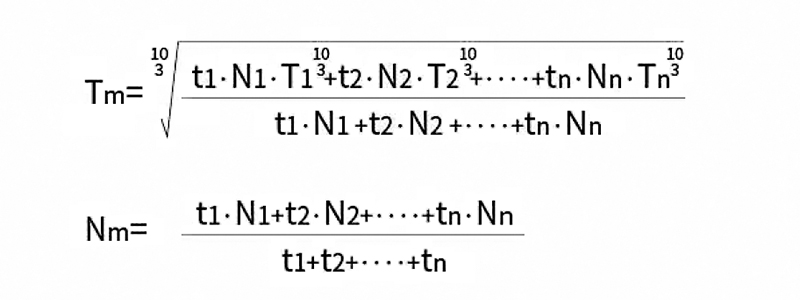
| At startup (MAX) |
When stable | When stopped (MAX) |
When emergency stop impact |
|
|---|---|---|---|---|
| Load torque (Nm) |
T1 | T2 | T3 | Tem |
| Speed (r/min) |
N1 | N2 | N3 | Nem |
| Time (sec) |
t1 | t2 | t3 | tem |
The wave generator includes a structure of a European-style coupling with a self-aligning structure and an integrated type without an automatic self-aligning structure, and varies depending on the series. For details, please refer to the outline drawing of each series.
Basic structure and shape of wave generator shown as below
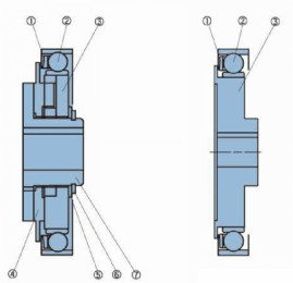
Structure of cross sliding block type-using European coupling structure
- Holder of flexible bearing
- Flexible baring
- Wave generator
- Cross sliding block
- Gasket
- Ring-shield
- Power input shaft
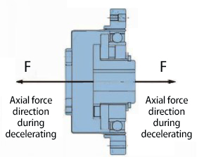
Axial force and axial fixation of wave generator
The axial force on wave generator begins to work due to elastic deformation of flex spline.
When used as a reducer. the axial force moves towards to the inside of the flex spline.
When used as a speed increaser, the axial forces movement is opposite to the direction of the deceleration.
The design of prevent axial force of wave generator shall be adopted under any conditions of usage.
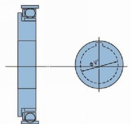
Maximum apperture size of the unibody wave generator
The standard aperture of the wave generator has shown in the outline drawing, the alteration can be made within maximum size range shown in the table.
We suggest to use GB standard for keyway size. The key's effective length dimension should be designed to fully withstand the value of the transmitted torque.
| Model | 11 | 14 | 17 | 20 | 25 | 32 | 40 |
|---|---|---|---|---|---|---|---|
| Standards size (H7) | 5 | 6 | 8 | 9 | 11 | 14 | 14 |
| Minimum size | - | 3 | 4 | 5 | 6 | 6 | 10 |
| Maximum size | - | 8 | 10 | 13 | 15 | 15 | 20 |
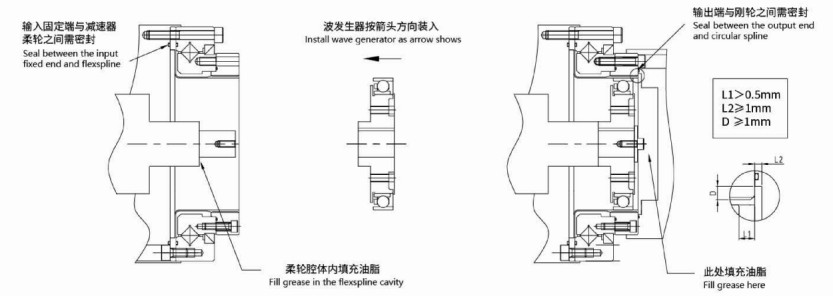
Installation Procedure
Installation of WSS series
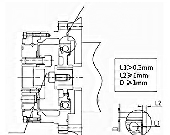
The first method of installation for WHT-I/II series reducer
The second method of installation for WHT-I/II series reducer
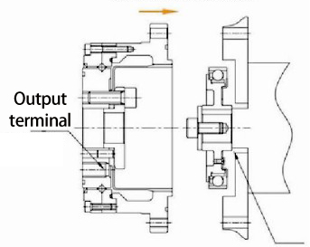
 Fill grease here
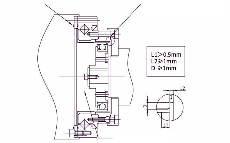 Fill grease in the flex spline cavity
The connecting and fixing method of wave generator
1. Input shaft has a shaft shoulder, it can be connected with wave generator directly. As shown in the figure.
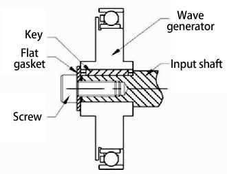
2. Input shaft has a shaft shoulder, but it's too long. You can add a space ring on the shaft (the parallelism of space ring should be within 0.01mm), then connect and fix the wave generator. As shown in the figure.

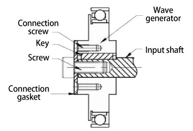
3. Input shaft has no shaft shoulder. Fix a connection gasket on the wave generator, then connect and fix with the input shaft. As shown in the figure.
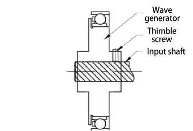
4. The fixing method is suitable for small models, optical axis input. Input shaft inserted into the wave generator, then connect and fix it through the thimble screw on wave generator. As shown in the figure.
Assembly Considerations
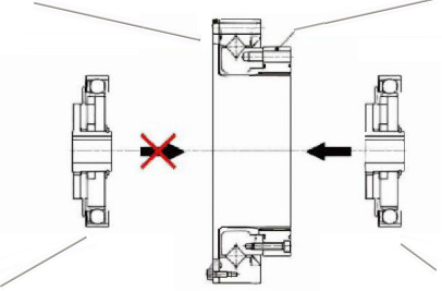
Assembly procedure
Instals the circular spline and flex spline on the device, and then instal the wave generator. Otherwise it may cause stuffing damage to the gear teeth or improper eccentric gear mesh. Please pay close attention to it.
Precaution on wave generator
1. Please avoid applying undue force on the bearing on wave generator during assembly. We suggest to rotate the wave generator while inserting, it will case the process.
2. If the wave generator does not have an oldham coupling, extra care must be given to ensure that concentricity and inclination are within the specified limits.
Precautions on circular spline
1. Mounting surfaces need to have adequate flatness, smoothness, and no distortion.
2. Especially in the area of the screw holes, burrs or foreign matter should not be present.
3. Please make sure the chamfering and avoidance machining are performed on the housing assembly, to avoid the interference with the circular spline.
4. The circular spline should be rotatable within the housing. Be sure there is no interference and it does not catch on anything.
5. When mounting the bolt, make sure the bolt hole is correct and aligned Bolts should rotate freely when tightening and should not have any irregularity due to the bolt hole being misaligned or oblique.
6. Don't tighten the bolts with the specified torque all at once. Tighten the bolts temporarily with about half the specified torque, and then tighten them with the specified torque. Tighten them in an even, crisscross pattern.
7. Avoid pinning the circular spline if possible as it can reduce the rotational precision and smoothness of operation.
Precautions on flex spline
1. Mounting surfaces need to have adequate flatness, smoothness, and no distortion.
2. Especially in the area of the screw h oles, burrs or foreign matter should not be present.
3. Please make sure the chamfering and avoidance machining are performed on the housing assembly, to avoid the interference with the circular spline.
4. When mounting the bolt make sure the bolt hole is correct and aligned. Bolt ros should tate freely when tightening and should not have any irregularity due to the bolt hole being misaligned or oblique.
5. Don't tighten the bolts with the specified torque all at once. Tighten the bolts temporarily with about half the specified torque, and then tighten them with the specified torque. Tighten them in an even, crisscross pattern.
6. Avoid unilateral meshing and deviation when assembling with circular spline.
Rust prevention
The complete assembly unit has no rust prevention on surface. Please daub anti-rust if needed. Besides, if an anti-rust product is needed, please contact with the authorized distributor.
Assembly accuracy of WSS series
To make sure LSS series play its excellent performance when assemble, please make sure to use the following accuracy.
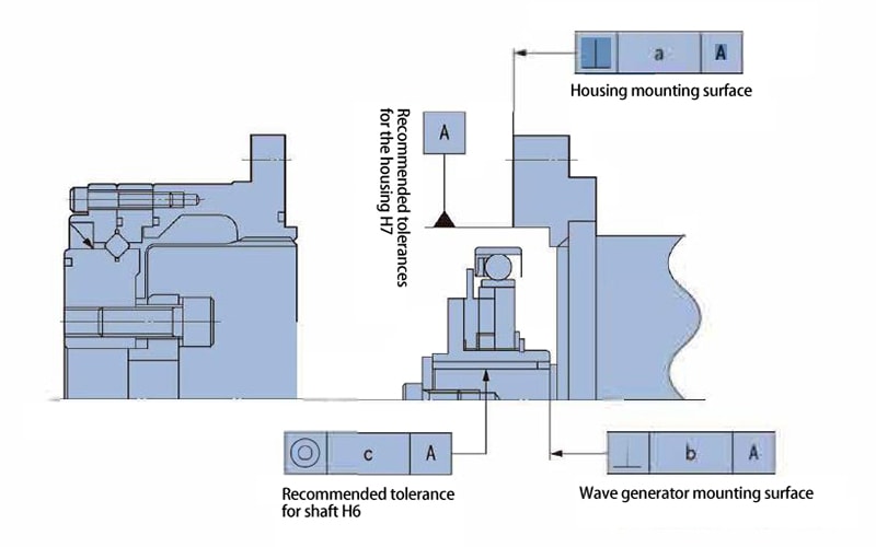
Recommended accuracy of the assembled housing
| Symbol / Model |
14 | 17 | 20 | 25 | 32 |
|---|---|---|---|---|---|
| a | 0.011 | 0.015 | 0.017 | 0.024 | 0.026 |
| b | 0.017 | 0.020 | 0.020 | 0.024 | 0.024 |
| (0.008) | (0.010) | (0.010) | (0.012) | (0.012) | |
| c | 0.030 | 0.034 | 0.044 | 0.047 | 0.050 |
| (0.016) | (0.018) | (0.019) | (0.022) | (0.022) |
Assembly accuracy of WHT series
To make sure LHT-I/II series play its excellent performance when assemble, please make sure to use the following accuracy.

| Symbol / Model |
14 | 17 | 20 | 25 | 32 | 40 |
|---|---|---|---|---|---|---|
| a | 0.011 | 0.015 | 0.017 | 0.024 | 0.026 | 0..026 |
| b | 0.017 | 0.020 | 0.020 | 0.024 | 0.024 | 0.032 |
| (0.008) | (0.010) | (0.010) | (0.012) | (0.012) | (0.012) | |
| c | 0.030 | 0.034 | 0.044 | 0.047 | 0.050 | (0.050) |
| (0.016) | (0.018) | (0.019) | (0.022) | (0.022) | (0.024) |
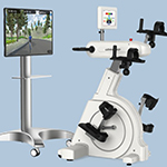
Application Industry
Suitable for a wide range of applications
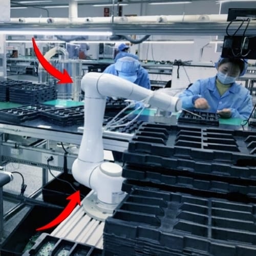
Cooperative Robot
Multi-articular machine
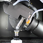
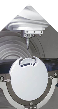
Laser Cutting Machine
Machine tool,Grinding mach-ines
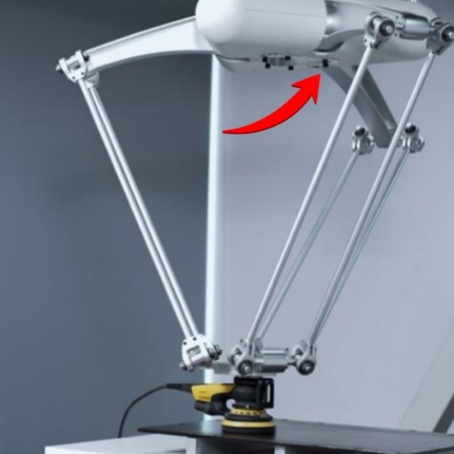
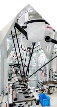
PARALLEL MANIPULATOR
Scara robots,spider hand...
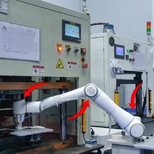
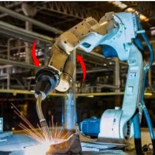
INDUSTRIAL ROBOT
Manipulator,axis robot etc

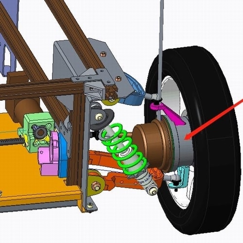
HUMANOID ROBOT
Bionic robot,walking robots
AGV CAE
Warehouse logistics AGV car
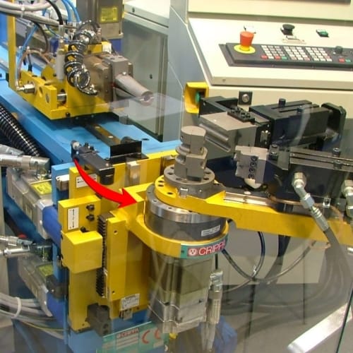
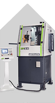
MACHINE TOOL
Pipe bending machine...
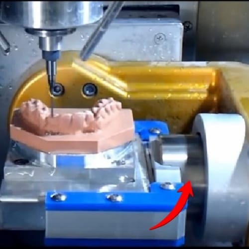
CNC Carving Machine
Denture carving and printing
EXTERNAL ROBOTS
rehabilitation bobot...
Factories of Fubao Mechanic Tech

Quote Now